System Architecture
Introduction
The proposed openENOC system architecture is motivated by the need for a scalable and modular communication substrate for modern MPSoC platforms. As the number of integrated processing elements, accelerators, memories, and peripherals continues to grow, traditional shared buses and point-to-point interconnects become increasingly difficult to scale in terms of bandwidth, latency, and design complexity. For this reason, the Network-on-Chip (NoC) paradigm has become a widely adopted architectural direction for complex SoCs, replacing ad hoc global wiring with structured packet-switched communication and better supporting system expansion and integration [1].
The openENOC architecture is based on an Ethernet-inspired Network-on-Chip (NoC) that uses Layer-2 Ethernet frame switching to interconnect CPUs, accelerators, peripherals, and memories within scalable MPSoC systems through a uniform communication model. This approach allows both on-chip and off-chip communication to be handled in a consistent way, making the architecture modular, extensible, and well suited for heterogeneous computing platforms targeting cryptography, AI, and edge workloads.
This architectural choice is further supported by the increasing heterogeneity of contemporary computing systems. Modern workloads combine general-purpose processors with specialized accelerators, producing communication patterns that are more diverse and demanding than those in conventional multicore designs. Recent research shows that NoC architectures for heterogeneous systems must provide flexible and scalable transport mechanisms capable of efficiently supporting different traffic types and bandwidth requirements [2]. Designing openENOC as an Ethernet-switched communication backbone directly addresses these needs.
The decision to adopt Ethernet-inspired Layer-2 frame switching is also practical from both implementation and system-design perspectives. Ethernet-switched communication improves modularity and composability because system components interact through standardized frames rather than tightly coupled dedicated links. Prior work on scalable interconnection architectures has shown the value of using common Ethernet-switched communication mechanisms across both on-chip and off-chip domains, improving system integration and extensibility in complex MPSoC platforms [3]. This makes Layer-2 switching a suitable foundation for an open and extensible hardware communication fabric.
Recent open-source NoC research also highlights the importance of scalable transport, support for parallel data streams, and efficient handling of both high-throughput and latency-sensitive traffic in accelerator-rich systems [4]. These observations are aligned with the goals of openENOC, which seeks to provide a unified interconnect for CPUs, accelerators, peripherals, and memories across a broad range of application domains.
Finally, the proposed architecture is consistent with broader trends in open heterogeneous SoC design, where modular integration, standardized interfaces, and FPGA prototyping are key enablers for experimentation and deployment [5]. In this context, the term Ethernet-based NoC denotes a packet-switched architecture implemented using Layer-2 Ethernet frame switching, providing a forward-looking balance between scalability, implementation simplicity, and system interoperability.
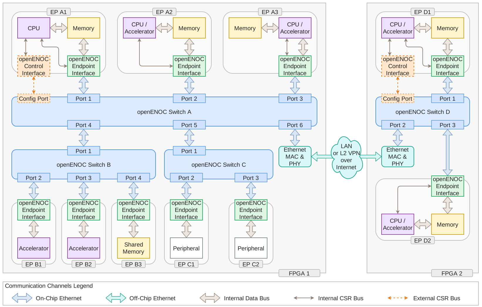
Overall openENOC System Architecture
The architecture illustrated above is built around four main building blocks: the openENOC Switch, the openENOC Switch Interface, the openENOC Endpoint Interface, and the openENOC Transport Protocol (oETP). Together, these building blocks separate forwarding, management, endpoint adaptation, and transport semantics into independent architectural layers.
This chapter presents a system-level architectural overview of openENOC and introduces the major architectural components and their relationships. Detailed implementation and protocol specifications are provided in subsequent chapters.
openENOC Switch
The openENOC Switch is the central frame-switching element of the openENOC architecture that connects processors, accelerators, peripherals, and memories through the openENOC Endpoint Interface. It supports an arbitrary number of ports and provides Layer-2 forwarding between attached components using Ethernet frame semantics. In this role, the switch forms the communication backbone of the openENOC architecture and establishes the substrate over which higher-level communication behavior can be built.
Two switch architectures are supported: shared-bus and crossbar. They provide the same Ethernet frame semantics, endpoint connectivity, and switch control interface, allowing each switch instance to balance hardware resources against the concurrency required by its traffic. The choice concerns the internal frame transport within a switch; the Ethernet-based NoC communication model and the oETP transport semantics remain common to both. Both architectures support unicast forwarding and multicast replication.
In the shared-bus architecture, incoming frames share one forwarding engine and one internal data path. A common forwarding table determines the output ports and supports source-address learning for autonomous operation.

openENOC Switch with shared-bus architecture
Sharing the forwarding engine and data path limits hardware duplication and interconnect complexity. This makes the shared-bus model suitable for compact FPGA implementations, peripheral subnetworks, and workloads with modest aggregate traffic. Its main limitation is that all ingress streams share the capacity of one internal path, even when their frames target different outputs. Increasing the number of ports therefore increases competition for that path. Once output buffering is exhausted, backpressure from a selected destination can stall the shared path and delay unrelated traffic.
In the crossbar architecture, each ingress has its own forwarding engine, while forwarding information remains shared. The internal fabric allows frames from different ingresses to advance concurrently when their destination sets do not overlap.

openENOC Switch with crossbar architecture
The crossbar model can provide higher aggregate throughput and reduce interference between independent streams, making it suitable for accelerator clusters and concurrent DMA or streaming transfers. This parallelism requires more forwarding logic and a larger interconnect, increasing FPGA resource use and implementation complexity as the port count grows. Frames competing for the same output still share that output’s bandwidth, and lookup and learning remain subject to shared table arbitration. Multicast traffic can also increase interference between streams that share destinations, while independent paths can continue.
The architecture is selected when the hardware is built. A common switch interface separates the surrounding NoC from the selected implementation. Future application-specific switch architectures can therefore be introduced without modifying the existing NoC topology, endpoint connections, or management integration, provided they preserve the common interface contract and Ethernet forwarding semantics.
Each switch in a hierarchical or multi-FPGA deployment may use the model appropriate to its own traffic profile. For example, the dedicated peripheral subnet described later in this chapter can use shared-bus switching to conserve resources, while a high-bandwidth accelerator subnet can use crossbar switching to carry independent transfers concurrently. A shared memory endpoint remains a common output bottleneck when all accelerators target it, so crossbar parallelism alone does not remove that bandwidth limit.
Independently of this hardware choice, both architectures can operate in two control modes:
Unmanaged mode: the switch operates autonomously and passively learns forwarding table entries from the traffic passing through it. This functionality is implemented by an integrated RTL controller that updates the forwarding state dynamically based on observed frames.
Managed mode: the switch is configured by an external processor connected through the openENOC Switch Interface. In this mode, MAC learning and forwarding behavior can be controlled using software-visible configuration mechanisms.
In addition to on-chip connectivity, switch ports may also be connected to Ethernet MAC & PHY controllers to extend communication beyond the chip boundary. This allows openENOC-based systems to scale from purely on-chip communication fabrics toward distributed multi-FPGA systems while preserving the same Ethernet-based forwarding model. As a result, the switch is not only the core of local communication, but also the bridge toward larger multi-device deployments.
openENOC Switch Interface
The openENOC Switch Interface is a memory-mapped interface used to configure and monitor the openENOC Switch. It exposes configuration and status registers (CSRs), the forwarding table, and related control structures required for managed operation. Through this interface, software can observe and influence the behavior of the switching fabric without changing the data-plane abstraction presented to the rest of the system.
When the switch operates in managed mode, a processor accesses this interface to define forwarding behavior, populate or update entries in the forwarding table, inspect switch state, and react to network events or topology-specific requirements. This enables software-defined traffic management while keeping the forwarding substrate modular and reusable.
Both shared-bus and crossbar switches expose the same management model. Software manages one forwarding table and one switch control interface in either case, independently of internal traffic arbitration and replication. The hardware architecture is fixed when the hardware is built, while managed and unmanaged operation can be selected at runtime.
In architectural terms, the switch interface complements the switch by separating control-plane responsibilities from frame forwarding. This distinction becomes especially important in systems where only selected endpoints require authority over the communication domain, while the remaining components interact with the network strictly through data exchange.
Systems that rely exclusively on autonomous switching behavior may omit the switch interface entirely and operate the switch in unmanaged mode.
openENOC Endpoint Interface
The openENOC Endpoint Interface is the termination point for Ethernet communication arriving from the openENOC Switch. Every resource attached to the openENOC fabric, including processors, accelerators, memories, and peripherals, is represented on the network through an openENOC Endpoint Interface. It provides both memory-mapped and streaming integration models, allowing different classes of compute and memory resources to connect to the common network in a manner appropriate to their communication style. On the local side, integration with processors, accelerators, and memory-mapped resources is provided through AXI4-Lite interface.
The internal structure of the openENOC Endpoint Interface is illustrated in the figure below. It consists of a CSR block, a DMA Engine, an oETP Engine, and supporting buffering logic that enables conversion between the memory-mapped access model used by the CSR and DMA Engine and the streaming transfer model used by oETP. This buffering logic absorbs processing latency and preserves transfer continuity during conversion between the two communication models. The CSR block provides configuration and control access to the endpoint, but may also support a passthrough path toward the AXI4-Stream (AXIS) interface, enabling a streaming integration model for low-latency dataflow-oriented components. In addition, the CSR block exposes a Remote Memory (RMEM) window for direct mapping of remote memory regions through the DMA Engine. This is useful in low-latency applications where simple, direct word access is preferred over descriptor-based bulk DMA transfers. The DMA Engine performs local memory access through AXI4 and RMEM CPUIF, while the oETP Engine handles protocol parsing and assembly. The AXIS path between the engines carries complete Ethernet frames without FCS for non-oETP DMA and only the addressed memory-block data for oETP DMA; RMEM words travel through the DMA command/completion interface.

Internal structure of the openENOC Endpoint Interface
Individual endpoint implementations may configure, specialize, or extend these internal blocks depending on the attached resource. For example, an endpoint connected to memory may use DMA functionality and local buffering for bulk data movement, while an endpoint connected to an accelerator may rely more heavily on protocol adaptation, streaming access, or application-specific processing logic. The endpoint abstraction therefore represents a generic attachment mechanism rather than a single fixed communication engine.
For memory-oriented deployments, endpoint implementations may operate in two common modes:
Standalone mode: the integrated controller autonomously handles DMA transfer coordination, memory range mapping, and data replication and synchronization.
Non-standalone mode: the endpoint is connected to a processor through its own AXI4-Lite CSR interface. In this case, the processor controls DMA-related functions such as interrupts, descriptors, and transfer management.
This makes the endpoint suitable both for memory-centric communication and for low-latency dataflow-oriented processing. More broadly, the Endpoint Interface forms the boundary between the Ethernet-based openENOC fabric and the local logic attached to the endpoint. On the network side, it terminates Ethernet frame exchange and handles oETP protocol processing. On the local side, it exposes the corresponding control, memory-mapped, DMA, or streaming access model through AXI4-Lite and AXI4-Stream interfaces.
openENOC Transport Protocol
The openENOC Transport Protocol (oETP) defines the transport-layer semantics of the architecture. It supports communication patterns such as remote memory access, processor-to-processor communication, accelerator integration, and transparent interconnection across multi-FPGA systems. While the openENOC Switch, openENOC Switch Interface, and openENOC Endpoint Interface define how components are connected and managed, oETP defines how memory-oriented transactions and related transport semantics are expressed over that Ethernet-based communication substrate.
Existing RDMA-over-Ethernet technologies, most notably RoCEv1, provide a natural starting point for Ethernet-based memory-centric communication. However, these protocols were originally designed for datacenter environments and inherit a significant portion of the InfiniBand transport model, including Queue Pair (QP) abstractions, work request management, connection state tracking, completion queues, and memory registration mechanisms [6]. Furthermore, RoCEv1 assumes a lossless Ethernet fabric and relies on Priority Flow Control (PFC) to prevent packet loss [7]. Multiple studies have shown that PFC can introduce head-of-line blocking, congestion propagation, and deadlock scenarios, increasing the complexity of both network infrastructure and endpoint implementations [8]. Such mechanisms are difficult to justify in Network-on-Chip environments, where buffering resources are limited and implementation simplicity is a primary design objective.
To address these limitations, the openENOC project introduces oETP, a lightweight transport protocol specifically designed for Ethernet-based NoC systems. Rather than adopting the complete RDMA transport stack, oETP focuses on a minimal set of communication primitives required in hardware-centric MPSoC environments. The protocol employs compact message headers optimized for the small transactions typical of NoC workloads, reducing communication overhead and hardware resource consumption.
The message structure used by oETP is illustrated in the figure below. The protocol is encapsulated directly within a standard Ethernet frame using an EtherType reserved for local experimental use. This enables protocol development and evaluation while retaining the Ethernet framing model used throughout the fabric.

oETP PDU Encapsulation
oETP retains the most valuable aspect of the RDMA programming model by supporting one-sided memory operations, including remote read and remote write transactions, while eliminating Queue Pair infrastructure and other InfiniBand-specific transport semantics. Its two memory access classes are transparent 32-bit Remote Memory (RMEM) operations and bulk DMA operations over byte-addressed memory regions.
Frame structure
An oETP PDU begins with a one-byte Magic field, followed by a one-byte Cmd field that identifies the operation. The remaining parameters are four-byte words whose meanings depend on the command. They identify the request and carry addresses, lengths, write masks, or memory data as required. Ethernet framing supplies the source and destination addresses, allowing the same transport format to serve on-chip and off-chip links.
Supported commands
The protocol provides request-response pairs for single-word RMEM reads and writes and for bulk DMA reads and writes, together with a common error response. The following table summarizes their codes, parameter order, and purpose.
Command |
Cmd |
Parameters, in order |
Operation |
|---|---|---|---|
RMEM_READ_REQ |
|
Request ID
Address
|
Read one aligned 32-bit word. |
RMEM_READ_RSP |
|
Request ID
Data
|
Return the complete word on success. |
RMEM_WRITE_REQ |
|
Request ID
Address
BitEnable
Data
|
Write selected bits of one aligned word. |
RMEM_WRITE_RSP |
|
Request ID |
Acknowledge a completed unicast write. |
DMA_READ_REQ |
|
Request ID
Address
Length
|
Read one remote memory fragment. |
DMA_READ_RSP |
|
Request ID
Data words
EndOfData
|
Return the requested fragment on success. |
DMA_WRITE_REQ |
|
Request ID
Address
Length
Data words
EndOfData
|
Write one remote memory fragment. |
DMA_WRITE_RSP |
|
Request ID |
Acknowledge a completed unicast fragment write. |
ERROR_RSP |
|
Request ID
Error Code
|
Report failure instead of a success response. |
RMEM operations access one aligned 32-bit word; writes can select individual bits through BitEnable. Bulk DMA operates on byte-addressed memory regions and can divide a larger transfer into fragments. A DMA read response uses the length saved with its request. EndOfData marks the end of successfully emitted bulk data in DMA write requests and DMA read responses.
Request sequencing and recovery
Version 1 uses sequential request-response transactions. A bulk transfer advances one fragment at a time after the current fragment completes. Each request has a Request ID that associates its response with the initiating operation. Endpoints continue servicing incoming requests while awaiting their own responses, supporting communication in both directions.
Unicast success confirms completion of the requested operation at the receiving endpoint. Failures are reported locally, and configurable response timeouts can bound waits for missing unicast responses. Software can use status and interrupt notifications to select recovery. Streaming memory transfers may leave partially updated buffers after an error; oETP does not provide rollback or whole-block atomicity. Software owns buffer synchronization and any deliberate retransmission. Version 1 has no automatic retransmissions or wire credits.
Multicast writes
RMEM and DMA writes can use multicast destinations for one-to-N memory replication. Each receiver applies its own access policy before updating local memory. Read operations use unicast destinations.
Multicast writes are best effort: receivers send no success or error responses, and sender completion confirms local emission rather than completion at every receiver. Group members share a multicast destination while retaining individual unicast identities for ordinary transactions and peer identification.
By combining Ethernet framing, sequential request-response transactions, and RDMA-style one-sided memory operations, oETP targets tightly coupled hardware systems rather than distributed datacenter infrastructure. Within openENOC, the protocol is intended to operate over both on-chip Ethernet links inside a single MPSoC or FPGA system and off-chip Ethernet links connecting multiple FPGA-based domains through external MAC & PHY components. This allows the same transport model to span both local and multi-FPGA deployments while preserving a consistent programming and communication model across the entire Ethernet-based architecture.
Architectural Relationships
At the system level, the openENOC Switch forms the communication backbone, while each functional block is attached through an openENOC Endpoint Interface. The openENOC Switch Interface is used where software-visible management of the switch is required, and the openENOC Transport Protocol (oETP) provides transport-level semantics for memory-oriented communication between endpoints across the same Ethernet-based fabric.
the switch forwards Ethernet frames between ports,
the endpoint interface adapts Ethernet frame-based communication to local computation, memory, or peripheral logic,
the switch interface provides optional software control over switch behavior,
the oETP defines lightweight transport semantics for higher-level communication patterns such as remote reads and writes.
This separation enables the architecture to scale in several directions: multiple endpoints can share a common switch, specialized switches can be introduced for subsystems with different bandwidth or latency requirements, software control can be centralized where necessary, and transport-level behavior can remain consistent across both local and distributed Ethernet-connected domains.
Example Configurations
The following examples refer to the architectural diagram shown earlier and illustrate representative ways in which openENOC components can be combined to address different communication and integration requirements.
EP A1: Managed switch operation with processor-coordinated DMA
EP A1 illustrates a configuration in which openENOC Switch A operates in managed mode. A processor is connected to the switch configuration port through the openENOC Switch Interface, and the corresponding endpoint uses DMA-capable communication through the openENOC Endpoint Interface.
This use case is suitable for systems that require explicit software control over network behavior, for example when traffic policies must be tuned at runtime or when integration with higher-level resource management software is required.
Because the switch provides only a single configuration port, this managed setup typically applies to one controlling endpoint in that switch domain. Other endpoints connected to the same switch, such as accelerators or memories, may still exchange traffic through the same fabric without direct access to switch management. In such a setup, oETP can provide a common transport abstraction for memory-oriented transactions while the processor retains control over switching policy.
EP A2: Data endpoint without switch control access
EP A2 shows a standard endpoint connected to openENOC Switch A without direct access to the switch interface. It still uses the openENOC Endpoint Interface for communication with integrated memory, processing, or peripheral logic, but relies on the switch behavior established elsewhere in the system.
This arrangement is useful when one software-visible control point manages a larger communication domain, while other endpoints remain focused on data exchange only. From the perspective of higher-level communication, such endpoints may still participate in oETP-based transactions even though they do not manage the switch directly.
EP A3: Direct processor/accelerator connection for streaming applications
EP A3 illustrates direct attachment of the openENOC Endpoint Interface to a processor or accelerator without using DMA. In this setup, incoming data is consumed directly by the computational logic, enabling a streamlined path between the network fabric and a latency-sensitive processing element.
This model is particularly suitable for streaming-oriented applications, where low-latency processing is more important than bulk memory transfers. Typical examples include packet inspection, signal processing, and accelerator pipelines operating on continuous data streams, and other workloads where data should be processed as it arrives rather than first copied into memory.
Switch C: Dedicated low-speed or hierarchical peripheral subnet
Some peripherals operate at substantially lower speeds than CPUs, accelerators, or memory subsystems. In such cases, attaching them directly to a high-performance switch may be inefficient. The architecture therefore supports dedicated lower-speed or hierarchical subnetworks that better match the requirements of peripheral communication.
In the diagram, EP C1 and EP C2 are peripheral endpoints connected to this lower-speed subsystem. This organization is also useful in hierarchical communication topologies, where different parts of the system are grouped according to bandwidth, latency, or functional role. In that sense, the arrangement is analogous to a northbridge/southbridge style decomposition in traditional computer architectures. Within such a hierarchy, the same endpoint abstraction is preserved even when the communication characteristics of the subnet differ from those of the primary switch domain.
Using dedicated peripheral switches improves modularity and allows each subsystem to operate at a communication rate appropriate to its role.
Off-chip scaling across multi-FPGA systems
The architecture also supports scaling beyond a single FPGA-based MPSoC. By connecting Ethernet MAC & PHY controllers to switch ports, communication can be extended from on-chip to off-chip domains while preserving the same Ethernet-based framing and switching model.
This enables multiple openENOC domains to be combined into a larger communication fabric while preserving the same endpoint abstraction. From the perspective of the endpoints, the communication model remains consistent, which simplifies the extension of software and hardware components from a local MPSoC setting to a distributed deployment. In this broader setting, oETP provides an especially important role by allowing the same lightweight transport semantics to span both on-chip and off-chip Ethernet links.
When FPGA systems are geographically distributed or connected through the Internet, the external network must provide Ethernet connectivity at Layer-2, which may require appropriate L2 VPN infrastructure depending on the deployment environment. Communication security in such deployments is outside the scope of openENOC itself and must be provided by the external network environment.
On FPGA 2, openENOC Switch D mirrors the same architectural principles used on FPGA 1. EP D1 shows a processor/accelerator plus memory subsystem with managed-switch capability through the switch interface, while EP D2 and EP D3 illustrate additional connected resources within the remote communication domain.
In other words, openENOC is not limited to a single-chip NoC; it can be extended into distributed Ethernet-connected multi-FPGA deployments. Because the same switch, endpoint, control, and transport concepts are preserved, the architecture remains conceptually uniform even as it scales from local integration to geographically distributed systems.
Development and Integration Flow
The openENOC project is designed around a model-driven development workflow that enables a consistent transition from hardware and software design to verification, system integration, and deployment. The development and integration flow shown below illustrates how the various project artefacts are generated and used throughout the design lifecycle.
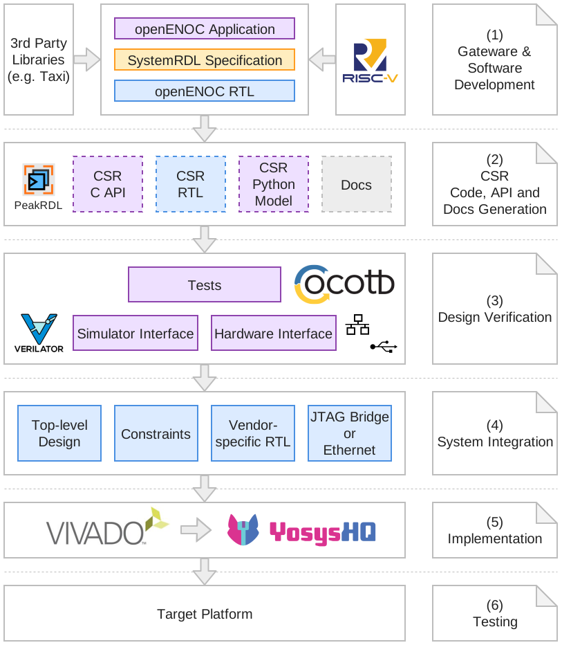
openENOC Development and Integration Flow
The process begins with the development of openENOC hardware and software components alongside a SystemRDL [9] specification for the Control and Status Register (CSR) interface, serving as the single source of truth for the register map and enabling automatic generation of implementation and verification artefacts using PeakRDL [10].
From the SystemRDL specification, the build system generates synthesizable CSR RTL, software-accessible CSR APIs, a Python register model, and associated documentation. This approach ensures consistency between hardware, software, and verification environments while significantly reducing manual maintenance effort.
The generated Python register model is integrated into the verification framework, which is based on cocotb [11] and Verilator [12]. Together with simulator interfaces, hardware interfaces, and automated test suites, this environment enables functional verification of individual openENOC components as well as complete subsystem configurations. By deriving verification artefacts from the same register specification used by hardware and software, the risk of inconsistencies between implementation and test environments is minimized.
To support continuous validation of the design, the verification infrastructure is intended to be integrated into a Continuous Integration (CI) workflow. Automated execution of simulation, verification, and build tasks enables functional regressions to be detected early and ensures that modifications to RTL, software components, register definitions, or verification infrastructure do not introduce unintended behavior. While GitHub Actions currently serves as the primary CI platform, the underlying procedures are designed to remain platform-independent. Verification and build workflows are implemented using portable scripts and standardized tooling interfaces, allowing them to be executed in alternative CI environments such as GitLab CI, Jenkins, Buildbot, or self-hosted automation systems without modification to the overall methodology.
Following successful verification, the generated RTL and openENOC components are integrated into a target platform design. This stage includes the creation of top-level designs, implementation constraints, vendor-specific integration logic, and external access mechanisms such as JTAG or Ethernet-based control interfaces.
The resulting design can then be processed using either vendor toolchains or open-source FPGA implementation flows to generate a deployable hardware image. Once programmed onto the target platform, the complete system can be validated using software-driven functional tests and application-level workloads.
This workflow establishes a unified development methodology in which hardware design, software development, verification, continuous integration, and deployment are derived from a common set of specifications. The approach improves maintainability, reproducibility, and scalability while facilitating collaboration across different hardware platforms, toolchains, and deployment environments.
Summary
Overall, the openENOC system architecture combines Ethernet-style frame switching with configurable endpoint integration and a lightweight transport model to provide a scalable communication substrate for heterogeneous MPSoC systems. The resulting design separates switching, control, endpoint adaptation, and transport semantics into distinct but cooperating architectural components.
The architecture supports several important deployment patterns, including software-managed switching, DMA-based memory transfers, direct streaming data paths, dedicated subnetworks for specialized traffic classes, and off-chip scaling across multi-FPGA systems. By introducing oETP alongside the existing switch and interface abstractions, openENOC establishes a transport layer suitable for efficient memory-centric communication across both on-chip and off-chip Ethernet domains.
A defining characteristic of openENOC is the use of a unified Ethernet frame-based communication model across both on-chip and off-chip domains, enabling the same architectural concepts to scale from individual FPGA devices to distributed multi-FPGA systems. This approach promotes architectural consistency while simplifying integration with existing Ethernet-oriented hardware and software ecosystems.
Beyond the communication architecture itself, openENOC adopts a model-driven development methodology in which hardware, software, verification, and documentation artefacts are derived from a common set of specifications. Automated artefact generation, reusable verification infrastructure, and platform-independent Continuous Integration workflows help ensure consistency across the development lifecycle while improving maintainability, reproducibility, and portability. Together, these architectural and development principles provide a foundation for building scalable, verifiable, and extensible Ethernet-based interconnect systems.