Full endpoint – openenoc_endpoint_full
Combines a processor, local memories, register control, and transport into a complete reference endpoint.
Source:
openenoc_endpoint_full.sv.
Parameters
Name |
Default value |
Allowed values |
Description |
|---|---|---|---|
|
|
Empty string or readable memory file path |
Optional instruction-memory $readmemh initialization. |
|
|
Empty string or readable memory file path |
Optional data-memory $readmemh initialization. |
Signals
Interface ports contain channels in both directions. The table identifies the selected modport or stream role; member directions follow that interface.
Name |
Type |
Direction / role |
Description |
|---|---|---|---|
|
|
input |
Clock for this component or interface domain. |
|
|
input |
Active-high reset of transaction and control state. |
|
|
bidirectional (csr) |
Switch configuration, pause status, and forwarding-table CPU access. |
|
|
bidirectional; endpoint is side A |
Ethernet frame transport; this endpoint is side A. |
Architecture and operation
The reference endpoint combines PicoRV32, instruction/data RAM, generated
CSR/HAL blocks, and Endpoint interface – openenoc_endpoint_interface. Its public boundary is
clk, rst, switch_if for switch control, and eth_if for transport.
IMEM_INIT_FILE and DMEM_INIT_FILE optionally initialize memory using
$readmemh-compatible files.
All AXI, AXI4-Lite, and AXI-Stream data paths are fixed at 32 bits.
Elaboration checks require eth_if.DATA_W,
openenoc_endpoint_full_pkg::OPENENOC_ENDPOINT_FULL_DATA_WIDTH, and the
generated CSR data width to equal 32.
AXI and AXI4-Lite addresses are fixed at 32 bits. The generated endpoint and CSR address maps must fit in this address space; elaboration checks reject wider maps. Local RAM and CSR decode widths follow their mapped region sizes.
Memory depths, base addresses, and DMA infrastructure limits come from the generated endpoint packages. The AXI4-Lite interconnect has four initiators: CPU, DMA, debug/programming, and local RMEM execution through the DMA-owned CPUIF. Its three targets are DMEM, IMEM, and CSR, in that packed target order. Adapters connect the endpoint’s AXI/CPUIF boundaries to AXI4-Lite memory access.
Memory map and interrupt integration
The current generated configuration uses the following decode apertures. The
register map itself remains specified by HAL Architecture Specification; these addresses are
obtained from openenoc_endpoint_full_pkg and
openenoc_endpoint_full_csr_pkg.
Target |
Base address |
Decode aperture |
Crossbar target |
|---|---|---|---|
IMEM |
|
32 KiB |
1 |
DMEM |
|
32 KiB |
0 |
CSR |
|
8 KiB |
2 |
IMEM_INIT_FILE supplies the boot image; DMEM_INIT_FILE can independently
initialize data memory. The CPU initiator uses PicoRV32 wrapper – openenoc_picorv32 and its
native-to-AXI4-Lite adapter. The reserved debug/program initiator is currently
tied inactive. DMA memory access uses an AXI4-to-AXI4-Lite adapter; received
RMEM access uses CPUIF to AXI4-Lite – openenoc_cpuif_axil_adapter. Both memory-access paths belong
to DMA, while oETP performs protocol processing.
All four initiators have read and write connectivity to all three targets. IMEM is therefore writable through the interconnect; its name does not imply a read-only region. The reserved debug initiator issues no requests and is not exposed as a programming port on this module.
The endpoint interrupt drives processor irq[3] as a level-sensitive source;
inputs 0..2 remain available for the core’s internal interrupt sources. The
generated capability reports info.irq_supported = 1. Processor eoi does
not retire an endpoint claim: software completes its exact token through
irq.complete. The platform reset vector is 0x0 and its interrupt vector
is 0x10. The software interrupt wrapper saves the interrupted context,
calls openenoc_endpoint_irq_handler, restores the context, and returns with
retirq.
Functional scenarios
The examples use the generated 32-bit memory map above. Bus labels are
local to each diagram. clk is the common endpoint clock; numbered
intervals end at the rising edge that samples their values.
Memory initialization, reset, and firmware boot
Each RAM is initially zero-filled and then optionally loaded from its
$readmemh file. This initialization precedes CPU execution; asserting
rst clears transaction state without reloading either memory image.
A valid boot image must already be present in IMEM when reset is released.
u_cpu.resetn is the inverse of rst. The processor starts at
A0 = IMEM_BASE_ADDR and fetches instruction word D0 through
cpu_axil_if, crossbar initiator 0, and IMEM target 1. The pending
read address remains stable until arready; rvalid && rready
then transfers the instruction to the CPU adapter.
The platform startup code establishes the stack and global pointer,
copies initialized .data from IMEM into DMEM, clears DMEM .bss,
and calls main. These software stores can overwrite locations loaded
through DMEM_INIT_FILE. The configured stack top is just above the
DMEM aperture. Returning from main enters the startup code’s terminal
loop.
Processor access to instruction memory, data memory, and registers
Instruction fetches, data accesses, and HAL register accesses all use
the same cpu_axil_if. The crossbar decodes the address for each
transaction: A0 is an IMEM instruction address, A1 a DMEM word
address, and A2 a CSR register address. A representative sequence can
read instruction D0, write data D1 to DMEM, and read CSR value
D2.
The CPU adapter accepts one native request at a time and keeps its address
and write data until the AXI4-Lite transfer completes. Write address and
write data are independent channels: the example accepts awaddr
before wdata, with wvalid retaining D1 until wready.
wstrb = 0xF enables all four bytes. The CPU request finishes on the
write response, or on the read-data response for a load.
CSR reads and writes reach the generated register block at target 2.
Its bridge passes switch control through the public switch_if and
endpoint commands/status through the internal endpoint_if. DMA and
local RMEM use their own initiator ports to access the same mapped
targets; they do not pass through the processor’s native request channel.
Direct frame loopback with continuous and stalled transport
Software supplies and receives direct raw frames through the CSR stream
APIs. The endpoint interface buffers them and connects them to eth_if.
The external loopback returns side A’s transmit direction to its receive
direction without modifying accepted payload bytes. Direct receive mode
accepts the frame, and no raw RX DMA descriptor is armed in this example.
The diagram illustrates the firmware’s 66-byte frame on the 32-bit link,
using 16 full beats and one final beat with two valid bytes. The frame length excludes
preamble, SFD, and FCS. DA0, DA1, … are transmit
words and DB0, DB1, … the corresponding returned words, with
DBi = DAi on every accepted loopback beat.
The loopback pauses in cycles 5 and 6.
It deasserts TX tready and suppresses RX tvalid, even though
the endpoint’s RX tready remains asserted. TX retains DA4,
tkeep = 0xF, and tlast = 0 until cycle 7 accepts that beat;
the returned word DB4 is accepted at the same edge. The final
beat DA16/DB16 transfers in cycle 19 with tkeep = 0x3 and
tlast = 1. All preceding beats have tkeep = 0xF.
The firmware’s direct RX callback can begin reading CSR payload words before the final Ethernet beat arrives. Firmware masks CPU IRQs while submitting a direct TX frame and unmasks after submission, so a blocking RX callback cannot preempt the work needed to finish that loopback frame. Endpoint events remain queued while CPU IRQs are masked.
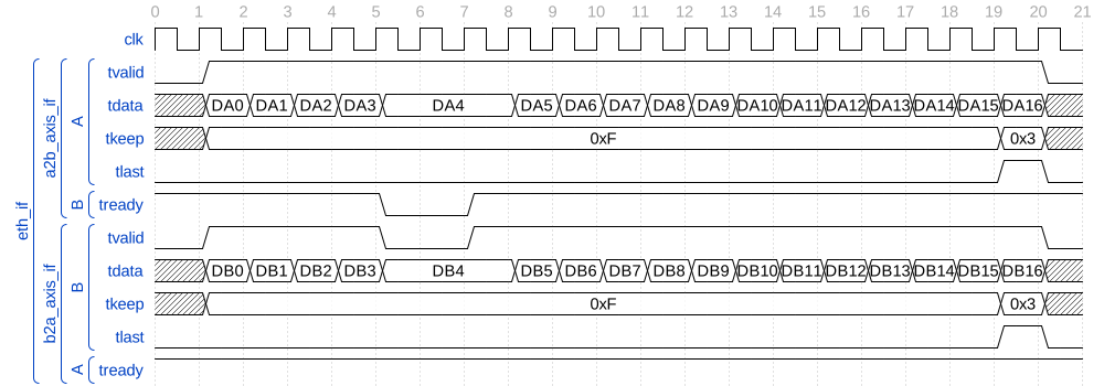
A 66-byte Ethernet loopback frame retained across transport backpressure
Interrupt entry, Ethernet reception, and claim completion
The example follows the firmware’s aligned direct-stream loopback test.
The first received word becomes visible through axis_if.sink and
produces a NON_OETP_DIRECT_RX_AVAILABLE notification, source 4,
with peer index zero. Notification does not wait for the whole Ethernet
frame. Firmware masks CPU IRQs while submitting the TX frame, then
unmasks them so the receive callback can drain the returning frame.
The controller’s endpoint_irq directly drives cpu_irq[3].
The CPU enters the vector at 0x10 and the platform wrapper saves
context in DMEM before calling openenoc_endpoint_irq_handler.
u_cpu.eoi[3] stays asserted until retirq; this unconnected CPU
output does not complete an endpoint claim.
The HAL reads RX claim word D0 and dispatches handle_event,
which increments the source’s event count and calls receive_axis_frame.
That callback invokes openenoc_endpoint_axis_receive_stream with
a 66-byte receive buffer. For each word, the receive function waits for
control.tready = 0 and status.tvalid = 1, reads data.tdata,
status.tkeep, and status.tlast, then sets control.tready.
Hardware consumes that word and clears the ready command through
control.tready.hwclr. Software stores the valid bytes into the DMEM
receive buffer in byte-lane order.
The 66-byte frame requires 17 word handshakes: DB0 through DB15
have tkeep = 0xF and tlast = 0; DB16 has tkeep = 0x3
and tlast = 1. After the final word, the callback records
axis_received_bytes = 66 and sets
axis_frame_received = true before returning.
Only after the callback returns does the HAL call
openenoc_endpoint_irq_request_complete with the saved RX claim.
It validates the current claim identity and writes the same
valid/sequence/source/peer fields to irq.complete. This call submits
the command without waiting for hardware to clear complete.valid.
The controller retires the matching claim and acknowledges the command
through complete.valid.hwclr.
In this ordering, a direct TX-completion claim D1
(source 3, peer index zero) is already queued behind RX claim D0.
It becomes the new head when D0 is completed, so the level IRQ stays
asserted after reception. The HAL also dispatches the TX callback and
submits its completion. Once no claims remain, the IRQ falls; the wrapper
restores context and executes retirq when the handler returns.
Claim sequences are part of D0/D1 and need not start at zero.
Back in test_axis_stream_loopback, firmware checks that reception
returned OPENENOC_ENDPOINT_STATUS_OK, the received byte count is 66,
the payload matches the transmitted bytes, and the buffer canaries remain
intact. The separate overflow test uses a 65-byte buffer for the same
66-byte frame and verifies that the function drains through the final
word while reporting OUT_OF_RANGE.
After all test groups complete, firmware masks CPU IRQs, confirms that
the IRQ controller is idle, and publishes 0x600D600D in
_openenoc_assert_status.status at u_dmem.mem[0]. The default
acceptance configuration reports completed_checks = 0x7F with zero
failure line and filename pointer. Returning from main leaves the
report stable in the terminal loop with cpu_trap = 0. An assertion
failure publishes 0xBAD0BAD0 and diagnostics before trapping.
Verification
The test suite is in dv/endpoints/openenoc_endpoint_full/.
Testbench
This cocotb suite verifies the openenoc_endpoint_full SoC wrapper by booting
sw/apps/endpoint_test PicoRV32 firmware and looping Ethernet TX back to RX. It checks
continuous transport, periodic backpressure, IRQ claim identity, and the final DMEM report.
The corruption case verifies assertion diagnostics after an injected payload error and a
subsequent CPU trap. All cases use fixed 32-bit AXI, AXI4-Lite, and Ethernet data paths.
Firmware checks are described in sw/apps/endpoint_test/README.md.
The firmware checks configuration, peer mappings, RMEM loopback and timeouts, direct streams, raw DMA, fragmented peer DMA push/pull, and IRQ service. Each successful loopback case transfers three 66-byte direct-stream frames, a fourth 66-byte raw-DMA frame, and 22 oETP frames. Direct RX notification and CSR payload reads may precede the final Ethernet beat.
The endpoint contains a 4-by-3 pipelined openenoc_axil_crossbar. System initiators are
ordered as PicoRV32, DMA, the reserved debug/program master, and local RMEM access from the oETP
path. Targets are ordered as DMEM, IMEM, and CSR. The suite checks activity on both DMA and RMEM
memory initiators while the debug initiator remains inactive. All initiators have read/write
connectivity to all three targets.
The generated CSR hwif is internal to the endpoint. An openenoc_endpoint_if instance
connects the generated CSR bridge to openenoc_endpoint_interface, while the module exposes
the bridge’s openenoc_switch_if side. The testbench drives pause_done through that
switch interface and observes its propagation into the CSR hwif.
The endpoint interface connects direct CSR AXI4-Stream transfers and DMA traffic to the
Ethernet-like link through buffered stream paths and the oETP engine. Four synchronous
taxi_axis_fifo_adapter instances buffer the direct and DMA transmit/receive paths. The
testbench loops the transmit direction back into the receive direction, with optional
backpressure or payload corruption.
The crossbar arrays use individually named internal Taxi interfaces: cpu_axil_if,
endpoint_axil_if, debug_axil_if, dmem_axil_if, imem_axil_if, and
csr_axil_if. DMA reaches endpoint_axil_if through a taxi_axi_axil_adapter; local
RMEM reaches the fourth initiator through rmem_cpuif and openenoc_cpuif_axil_adapter.
The CPU initiator uses the openenoc_picorv32 drop-in wrapper around the original PicoRV32
core and the project AXI4-Lite adapter. The suite checks endpoint firmware execution and
processor interrupt entry/return through this path.
Coverage
The firmware exercises configuration and capability checks, peer mapping and error clearing, direct RMEM self-loopback and timeout, AXIS stream APIs, raw DMA TX/RX, peer DMA push/pull and timeout, and IRQ handling. The default full endpoint completes all seven coverage groups.
The cocotb checks include:
booted instruction memory, successful execution without CPU traps, and stable final firmware result;
CPU instruction fetches, data-memory accesses, and CSR HAL calls reaching IMEM, DMEM, and CSR through the crossbar;
all coverage bits set (
0x7f) and no failing source file or line on success;three 66-byte direct AXIS frames using stream APIs: aligned buffers, unaligned buffers, and a 65-byte RX buffer with overflow drain, full byte count and canaries;
a fourth 66-byte raw Ethernet frame transferred through TX/RX DMA, with exact payload, byte masks and final TLAST;
17 AXI4-Stream transfers per raw frame, with
TKEEP=0xfon the first 16 words,TKEEP=0x3on the final partial word, andTLASTonly on that final word, in both Ethernet loopback and direct CSR receive traffic;22 oETP frames for transparent RMEM writes/reads, missing-destination timeouts, and three-fragment peer push/pull transfers;
exactly three direct frames on the CSR RX path, excluding the DMA-routed frame;
active DMA and RMEM memory masters while the reserved debug master stays idle;
RX notification before the frame’s final Ethernet beat and CSR payload reads within the IRQ handler;
12 acknowledged claims with ordered sequences 0 through 11: three peer-DMA, one raw TX, one raw RX, three direct TX, three direct RX and one RMEM error;
peer indices for timeout, push and pull events, claim-identity matching at completion, CPU IRQ entry/return, and no overflow or invalid completion;
empty IRQ FIFO and reservation state with the output deasserted after success;
generated switch dimensions on
openenoc_switch_if,pause_donepropagation into the CSRhwif, and endpoint MAC configuration;unchanged reset values of unrelated root test/switch registers, including
csr.test_regremaining zero;observed backpressure in the stalled case.
The assertion-failure case flips one payload bit in the first direct AXIS frame. It checks the
exact source filename and line, completed coverage 0x07, failure publication before the CPU
trap, and stable diagnostics after the trap.
All cases use the same debug firmware. Each run allows up to 500,000 execution cycles after reset.
Firmware Report
The testbench exposes the four DMEM words of _openenoc_assert_status, defined through the
shared assert.h:
Word |
Signal |
Firmware field |
|---|---|---|
0 |
|
|
1 |
|
|
2 |
|
|
3 |
|
|
Success requires status 0x600d600d, coverage 0x7f, failure line zero and a null filename
pointer. Status 0xbad0bad0 reports firmware failure before a CPU trap; the diagnostic
includes its source file, line, completed groups and observed beat counts. The filename is
decoded from the loaded firmware image. Status zero means execution has not yet published a
final result.