AXI4-Lite to CPUIF – openenoc_axil_cpuif_adapter
Bridges AXI4-Lite register accesses to a native CPU register interface.
Source: openenoc_axil_cpuif_adapter.sv.
Parameters
Name |
Default value |
Allowed values |
Description |
|---|---|---|---|
|
|
Integer >= 2 |
Number of buffered CPUIF responses, including reserved active-operation capacity. |
Signals
Interface ports contain channels in both directions. The table identifies the selected modport or stream role; member directions follow that interface.
Name |
Type |
Direction / role |
Description |
|---|---|---|---|
|
|
input |
Common sampling clock for the AXI4-Lite and CPUIF interfaces. |
|
|
input |
Active-high synchronous reset of request buffers, the active operation, and queued responses; immediately inhibits request acceptance and dispatch. |
|
|
bidirectional (wr_slv) |
Incoming AXI4-Lite write channels. |
|
|
bidirectional (rd_slv) |
Incoming AXI4-Lite read channels. |
|
|
bidirectional (mst) |
Native register-access master toward the target. |
Architecture and operation
s_axil_wr and s_axil_rd are AXI4-Lite slave views; m_cpuif is the
native master. The adapter has one fall-through buffer for each of AW, W,
and AR. AW and W can arrive in either order. A write becomes eligible only
after both its address and data are available; a read needs only AR.
An empty buffer can pass a channel directly into a CPUIF request without
an extra registered request stage. A consumed buffered item can be replaced
by a new AXI handshake at the same edge.
When a read and a complete write are both eligible, round-robin selection chooses the opposite of the previously dispatched operation type. The first tie after reset selects the read. An unpaired AW or W does not block a read. Only one CPUIF operation is outstanding, but the next operation can launch in the interval that acknowledges the preceding one.
m_cpuif.req is a dispatch strobe. Address, operation type, write data,
and bit enables are valid with that strobe; they need not remain unchanged
while an acknowledgement is pending. An otherwise idle target may acknowledge
in the request interval or after a delay. During a completion/dispatch
overlap, the acknowledgement belongs to the old operation, and the newly
issued operation remains pending for its own acknowledgement.
Connected AXI4-Lite and CPUIF address/data widths must agree. DATA width must
be a multiple of eight, with one AXI write strobe per byte. Addresses pass
through unchanged. Each WSTRB bit expands into eight CPUIF wr_biten
bits, so this adapter generates byte-granular native write masks.
AWPROT, ARPROT, and AXI request USER fields do not affect the native request;
BUSER and RUSER are zero.
Acknowledgements enter a single ordered response FIFO shared by reads and
writes. A CPUIF error becomes AXI SLVERR (0b10); otherwise the response
is OKAY (0b00). Read data is captured with rd_ack. The corresponding
AXI response becomes visible in the next clock interval when it reaches the
FIFO head. Only that head is presented: a held B response delays a later R
response even if RREADY is high, and the same rule applies in the other
direction. A response remains stable until its own VALID/READY handshake.
RESPONSE_FIFO_DEPTH counts both completed responses and the capacity
reserved for the active CPUIF operation. A completion converts the reserved
slot into a queued response. Dispatch requires space after accounting for
any response consumed at that edge. A full response FIFO therefore stops
CPUIF dispatch; the separate AXI request buffers can still accept their
next items. Consuming the FIFO head can permit a buffered request to launch
at the same edge. The minimum depth is two; the default is two.
Asserting rst immediately lowers AWREADY, WREADY, ARREADY, and CPUIF REQ.
At the next rising edge it clears buffered requests, the active operation,
and queued responses. BVALID and RVALID clear at that edge rather than
combinationally with reset. Aborted accesses do not receive fabricated AXI
responses. Reset must also cancel any old target operation before new traffic
resumes, so an acknowledgement from before reset cannot complete a new access.
Functional scenarios
The examples use 32-bit addresses and data, four byte strobes, and
RESPONSE_FIFO_DEPTH = 2. A numbered tick denotes a clock interval;
VALID/READY handshakes and CPUIF sampling occur at its ending rising edge.
Registered responses are shown in the following interval. x marks
payload or response fields that are irrelevant without their qualifier.
Labels A0, A1, … are byte addresses, and D0, D1, … are
data words. Labels are local to each scenario.
Independent AW and W arrival with delayed and immediate completion
Address |
Data |
Arrival order |
CPUIF completion |
|---|---|---|---|
|
|
AW in tick 1; W in tick 3 |
Delayed acknowledgement in tick 5 |
|
|
W in tick 7; AW in tick 9 |
Acknowledgement with the request in tick 9 |
The first AW handshake stores A0. No CPUIF request is issued until W
arrives with D0 and strobe S0 in tick 3. The stored address and
incoming data form the native write in that same interval. REQ is low
while the target waits, and wr_ack in tick 5 produces BVALID/OKAY
in tick 6.
For this 32-bit example, S0 = 0b0101 expands to
M0 = 0x00FF00FF, enabling bytes 0 and 2. The second write uses
S1 = 0b1111 and M1 = 0xFFFFFFFF. Its data is stored first, then
the incoming AW completes the pair in tick 9. A same-interval wr_ack
completes that request, and its B response follows in tick 10.
The read channels remain idle.
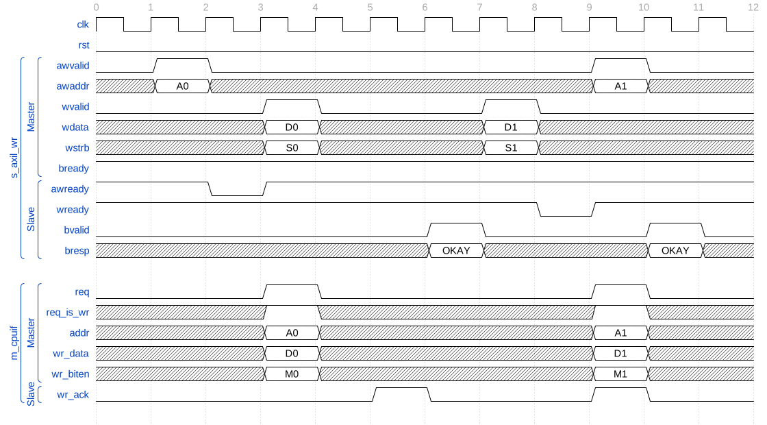
Either write channel can arrive first before native dispatch
Read/write selection and completion overlap
Both AXI response channels are ready throughout this example. All writes enable all four byte lanes.
Access |
Data |
AXI request accepted |
CPUIF dispatch / acknowledgement |
|---|---|---|---|
Read |
Returns |
Tick 1 |
Tick 1 / tick 3 |
Write |
|
AW and W in tick 1 |
Tick 3 / tick 6 |
Read |
Returns |
Tick 5 |
Tick 6 / tick 8 |
Write |
|
AW and W in tick 5 |
Tick 8 / tick 10 |
The simultaneous read and complete write in tick 1 select the read after
reset. AW and W are accepted into their buffers. In tick 3, rd_ack
returns D0 for A0 while REQ launches the buffered write to A1.
The read response is consumed in tick 4.
The next read and write are accepted in tick 5 while A1 is still active.
Its write acknowledgement in tick 6 permits the buffered read A2 to
launch. The acknowledgement in tick 8 returns D2 and launches write
A3. Thus each old completion and new request can share a sampling edge
without associating the old acknowledgement or read data with the new address.
Successful AXI responses follow in ticks 7, 9, and 11.
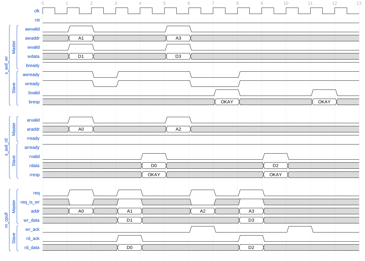
Read and write requests alternate across native completion edges
Ordered responses, errors, and a full response FIFO
All writes enable all four byte lanes. The target returns an error for the first write and the following read.
Access |
Data |
CPUIF dispatch / acknowledgement |
AXI response consumed |
|---|---|---|---|
Write |
|
Tick 1 / tick 3 |
B/SLVERR in tick 9 |
Read |
Returns |
Tick 3 / tick 5 |
R/SLVERR in tick 12 |
Write |
|
Tick 9 / tick 11 |
B/OKAY in tick 13 |
Write |
|
Tick 12 / tick 14 |
B/OKAY in tick 15 |
The B response for A0 is visible from tick 4, but BREADY remains low
through tick 8. The read completes in tick 5 with D1 and rd_err = 1.
RVALID stays low through tick 9 because the earlier B response is still
at the FIFO head, even though RREADY is initially high.
Both response slots are occupied from tick 6. AW and W for A2 are still
accepted in tick 6, but CPUIF REQ remains low. The next AW/W pair for A3
waits with VALID high in ticks 7 and 8 because those request buffers are full.
In tick 9, consuming the held B response frees capacity: A2 dispatches,
and the same edge accepts A3 into the request buffers it replaces.
The R response for A1 is then visible with stable D1 and SLVERR in
ticks 10 through 12. Its consumption in tick 12 permits A3 to dispatch.
The successful write responses for A2 and A3 follow in order. Errors
change the AXI response code without changing request pairing or data capture.
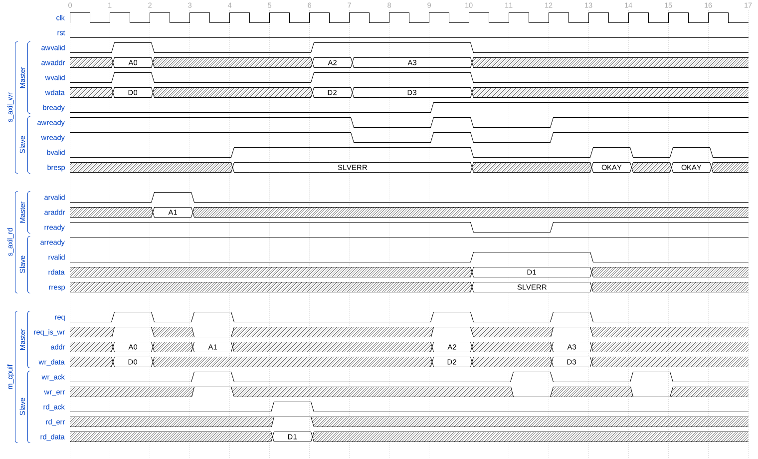
Ordered AXI responses reserve capacity before further native requests
Reset discards buffered, active, and completed accesses
The target cancels its outstanding operation during reset. AXI response consumption is paused so the first completed response is still queued. All writes enable all four byte lanes.
Access |
State before reset |
Result |
|---|---|---|
Write |
Completed in tick 3; B response held |
Queued response discarded |
Read |
Dispatched in tick 3; no acknowledgement |
Active operation cancelled |
Write address |
AW accepted in tick 5; no W received |
Partial write discarded |
Write |
W accepted after reset in tick 8; AW in tick 10 |
New request completes in tick 10 |
RST is high in ticks 6 and 7. Request READY signals and CPUIF REQ are already low in tick 6, while the held BVALID remains high until the first reset sampling edge. BVALID is zero in tick 7; no response is produced for the cancelled read.
After reset, D3 is accepted alone in tick 8. It cannot dispatch using
the old A2 address because that buffered AW was cleared. The new AW
for A3 arrives in tick 10 and pairs with D3. Its immediate native
acknowledgement produces the only post-reset B response, consumed in tick 11.
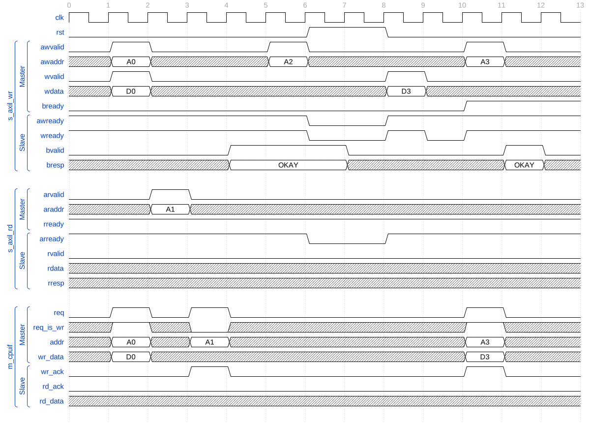
Reset removes old access state before a new write can dispatch
Verification
The test suite is in dv/core/openenoc_axil_cpuif_adapter/.
Testbench
This cocotb suite verifies openenoc_axil_cpuif_adapter in isolation with native CPUIF and
AXI4-Lite bus fixtures. The default fixture uses 32-bit addresses and data.
Coverage
The suite covers:
independent AXI write-address and write-data arrival;
fall-through dispatch when the second write channel arrives;
AXI byte-strobe expansion to CPUIF bit enables;
round-robin arbitration of simultaneous read and write requests;
same-cycle CPUIF completion and dispatch of the next operation;
zero-latency and delayed CPUIF acknowledgements;
ordered read and write response delivery;
simultaneous response dequeue and replacement;
response-FIFO saturation and CPUIF backpressure;
stable AXI read responses while backpressured;
CPUIF read and write error conversion to AXI
SLVERR;preservation of read response data; and
reset of AXI request buffers, the active CPUIF operation, and queued responses.