AXI4-Lite RAM – openenoc_axil_ram
Provides byte-writable on-chip memory through an AXI4-Lite slave interface.
Source: openenoc_axil_ram.sv.
Parameters
Name |
Default value |
Allowed values |
Description |
|---|---|---|---|
|
|
Integer > log2(STRB_W); slave address widths >= ADDR_W |
Byte-addressed aperture size is 2**ADDR_W bytes; data width comes from the AXI4-Lite interfaces. |
|
|
0 or 1 |
Adds a register to the RAM read response when set. |
|
|
Empty string or readable memory file path |
Optional $readmemh initialization; empty disables file loading. |
Signals
Interface ports contain channels in both directions. The table identifies the selected modport or stream role; member directions follow that interface.
Name |
Type |
Direction / role |
Description |
|---|---|---|---|
|
|
input |
Clock for this component or interface domain. |
|
|
input |
Active-high synchronous reset of bus state; stored memory is preserved. |
|
|
bidirectional (wr_slv) |
Incoming AXI4-Lite write channels. |
|
|
bidirectional (rd_slv) |
Incoming AXI4-Lite read channels. |
Architecture and operation
The interfaces provide a byte-addressed aperture of 2**ADDR_W bytes.
DATA and strobe widths come from the interfaces. The power-of-two strobe
count sets the word size. Word indexing drops the low byte-offset bits;
WSTRB selects the byte lanes actually written. High system-address
bits above the aperture are truncated, so addresses separated by an aperture
size alias the same storage. Reads return a complete word.
AW and W each have an independent single-entry fall-through buffer. A write commits when both are available and the B response stage has space. Empty buffers can supply the live AW/W values at that edge. If an older B response is held, one further AW/W pair can wait in these buffers. Consuming B can commit that queued write at the same edge and replace the response without an idle B interval. Responses are always OKAY; BUSER and RUSER are zero.
Reads use an elastic synchronous RAM output stage. With
PIPELINE_OUTPUT = 0, a read address accepted in one interval presents
RVALID and data in the next. With PIPELINE_OUTPUT = 1, a second elastic
register presents the response one interval later and can retain an additional
response. Both configurations sustain one read per cycle when unstalled.
Read payload and VALID remain stable until RREADY accepts them. Read and write
frontends progress independently for different memory locations.
Memory is initially zeroed, then a nonempty INIT_FILE is loaded with
$readmemh. File entries are full-width hexadecimal words; @ indices
refer to words, not byte addresses. Word i occupies byte address
i*STRB_W. Locations not supplied by the file retain zero. The file is
loaded during initialization and is not reloaded by transaction reset.
Reset inhibits request READY and write commits immediately. At the sampling edge it clears request buffers and B/R VALID state while preserving memory contents. A partially buffered write is discarded. Simultaneous read and write of the same word has no portable read-during-write value; an integration requiring a particular collision result must resolve that collision.
Functional scenarios
The examples use 32-bit DATA, four byte strobes, a 32-bit system address,
and ADDR_W = 8: a 256-byte aperture containing 64 words. The initialization
file supplies words D0, D1, and D2 at A0 = 0x00,
A1 = 0x04, and A2 = 0x08. A3 = 0x104 aliases A1.
Ticks are intervals ending at rising sampling edges; x marks fields
without VALID. Each scenario starts with transaction state reset.
Initialized reads and optional elastic output stage
The source offers reads of A0, A1, and A2 in order, while holding RREADY low through tick 5. Both configurations first accept A0 in tick 1. Without the extra stage, D0 is visible from tick 2 and prevents another AR until tick 6. With the extra stage, A1 is accepted in tick 2 and D0 is visible from tick 3; the second response occupies the other stage while RREADY is low.
Once RREADY rises in tick 6, both configurations deliver D0, D1, and D2 in ticks 6, 7, and 8. The non-pipelined configuration accepts A1/A2 in ticks 6/7; the pipelined configuration accepts its remaining A2 in tick 6.
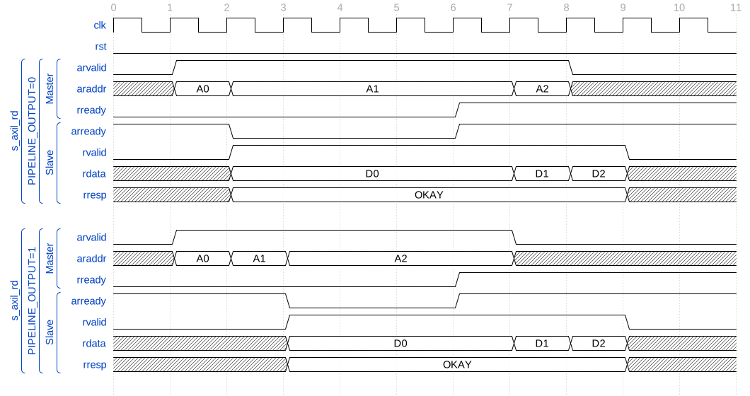
The optional output stage retains an additional initialized read response
Byte-enabled update and readback
This diagram uses PIPELINE_OUTPUT = 0. AW for A0 is accepted in tick 1;
W arrives with D3 and S0 = 0b0101 in tick 3. Bytes 0 and 2 are updated,
while bytes 1 and 3 retain their previous D0 values. The resulting word D4 is:
D4 = (D0 & 0xFF00FF00) | (D3 & 0x00FF00FF)
B/OKAY follows in tick 4. A read of A0 is accepted in tick 5 and returns D4 in tick 6. The same read would appear in tick 7 with the output pipeline enabled.
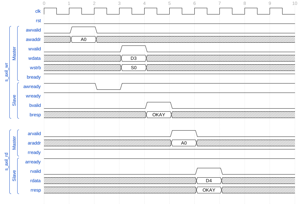
Write strobes update selected byte lanes before readback
Reset preserves committed memory and drops a queued write
This diagram uses PIPELINE_OUTPUT = 0. A full write of D3 to A1 commits
in tick 1, and its B response is held from tick 2. A read of A1 in tick 2
produces D3 from tick 3, also held by low RREADY.
A second AW/W pair for A2/D4 is accepted into the request buffers in tick 3. It cannot commit while the earlier B response is held. RST is high in ticks 4 and 5, clearing both responses and this queued write at the first reset edge. Memory retains the committed D3 at A1 and the original D2 at A2.
After reset, A3 is read in tick 6 and returns D3 in tick 7 because A3 aliases A1. A2 is read in tick 7 and returns the unchanged D2 in tick 8. Reset has neither erased the committed word nor applied the aborted buffered update.
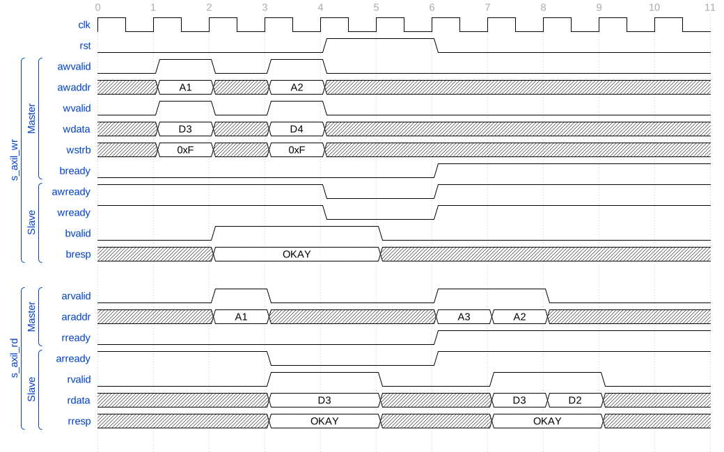
Reset preserves committed storage and discards a buffered update
Verification
The test suite is in dv/core/openenoc_axil_ram/.
Testbench
This cocotb suite verifies AXI4-Lite RAM with and without file initialization. The bundled
imem.mem provides a partial firmware image so the tests can check zero-filled locations
after the loaded contents. The default fixture uses 32-bit data, a 10-bit local aperture, and
32-bit bus addresses.
Coverage
The suite covers:
zero initialization when
INIT_FILEis empty;little-endian initialization from
imem.mem;zero filling after a partial initialization file;
8-, 16-, 32-, and 64-bit AXI4-Lite data widths;
read-response pipeline disabled and enabled;
aligned and unaligned accesses;
byte-strobe behavior through partial and cross-word writes;
first and last locations in the configured aperture;
truncation of upper system-address bits to the local RAM aperture;
memory-content preservation across reset;
independent and concurrent AXI read and write channels;
independent AW and W arrival timing;
bubble-free back-to-back AW/W and AR transfers when responses are accepted;
stable
BandRresponses while backpressured;request idle insertion and randomized channel/response backpressure;
deterministic randomized read/write stress;
OKAYread and write responses.