Address decoder – openenoc_axil_crossbar_addr
Decodes a memory address and access permissions into a crossbar target selection.
Source: openenoc_axil_crossbar_addr.sv.
Parameters
Name |
Default value |
Allowed values |
Description |
|---|---|---|---|
|
|
0..S_COUNT-1 |
Source index used for connectivity checks. |
|
|
Integer >= 1 |
Number of upstream initiator interfaces. |
|
|
Integer >= 1 |
Number of downstream target/output interfaces. |
|
|
>= max(1, ceil(log2(M_COUNT))) |
Width of the decoded target index. |
|
|
Integer >= 1 |
Byte-address width in bits; connected interfaces must agree. |
|
|
Integer >= 1 |
Number of decode regions per target. |
|
|
Packed aligned addresses; zero selects automatic placement |
One ADDR_W-bit base per target region; region index m*M_REGIONS+r starts in the least-significant slice. |
|
|
Zero, or 1..ADDR_W; crossbar integration also requires >= log2(STRB_W) |
Region span is 2**width bytes; zero disables the region. Packing follows M_BASE_ADDR. |
|
|
M_COUNT*S_COUNT-bit mask |
Permitted paths; bit m*S_COUNT+s connects source s to target m. |
|
|
M_COUNT-bit mask |
A set bit disallows nonsecure accesses to that target. |
Signals
Name |
Type |
Direction / role |
Description |
|---|---|---|---|
|
|
input |
Byte address to decode; forwarded addresses are not translated here. |
|
|
input |
AXI access attributes; bit 1 indicates a nonsecure access. |
|
|
output |
At least one permitted enabled target region matched. |
|
|
output |
Index of the matched target; meaningful only when match is set. |
Architecture and operation
The decoder maps addr and prot directly to match and select.
It is combinational, with no clock, reset, or retained request state. The
read and write
fabrics use its result to route requests or generate local decode-error
responses. S is a fixed source index for that decoder instance, rather
than a runtime input. S_COUNT sets the connection-matrix row width.
Each target has M_REGIONS region slots. Target m, region r occupies
slice m*M_REGIONS+r in M_ADDR_W and M_BASE_ADDR; target 0,
region 0 occupies the least-significant slice. Width w describes a
2**w-byte region. Width zero disables the slot regardless of its base
address. Any enabled region belonging to a target can select that target;
the output does not identify the particular region.
When the entire M_BASE_ADDR parameter is zero, enabled regions are
placed automatically in packed-slot order. Placement starts at address
zero. Each region starts at the next address aligned to its own size,
then advances the placement cursor to its end plus one. Disabled slots
do not advance the cursor. Alignment can leave unmapped gaps between
enabled regions of different sizes.
A nonzero M_BASE_ADDR parameter selects explicit placement for every
slot. An individual zero base then denotes a region starting at zero;
it does not request automatic placement for that slot. For an enabled
width w, the address comparison uses only bits above the low w bits of
the address and base. Supply aligned bases: an unaligned base describes
the aligned region containing it. The decoder does not reject overlapping
regions. If permitted regions from several targets match, the highest
target index wins. Use nonoverlapping regions for an unambiguous map.
An address match is eligible only if M_CONNECT[m*S_COUNT+S] is set.
When M_SECURE[m] is also set, prot[1] must be zero. PROT bits 0
and 2 do not affect the result. These checks apply to all regions of the
target. The read and write fabrics instantiate decoders with their own
connection matrices, allowing different permitted paths in each direction.
match = 1 means at least one enabled, connected, permitted region
matched. select is the binary-encoded target index, not a one-hot
bitmap. With no eligible match, both outputs are zero. A valid selection
of target 0 also has select = 0, so consumers must qualify it with
match. The standalone decoder has no data/strobe-width dependency;
the enclosing crossbar additionally requires regions to be at least one
AXI data word in size.
Functional scenarios
The examples use ADDR_W = 16, S_COUNT = 2, M_COUNT = 3,
M_REGIONS = 2, and SELECT_W = 2. M0, M1, and M2 denote targets
0, 1, and 2. Address labels are local to each scenario. Diagram columns
enumerate input cases, with the corresponding combinational output in
the same column; they do not represent clock cycles. Every displayed
select value is defined, including zero when match is low.
All examples share these region widths, packed from the highest slot to the lowest:
.M_ADDR_W({32'd8, 32'd9, 32'd8, 32'd10, 32'd0, 32'd8})
Automatic placement and alignment gaps
This example uses M_BASE_ADDR = '0, all connections enabled, and
M_SECURE = 0. The decoder instance has S = 0 and PROT stays zero.
Target |
Region |
Width |
Size |
Effective address range |
|---|---|---|---|---|
M0 |
0 |
8 |
256 bytes |
|
M0 |
1 |
0 |
Disabled |
No address space consumed |
M1 |
0 |
10 |
1024 bytes |
|
M1 |
1 |
8 |
256 bytes |
|
M2 |
0 |
9 |
512 bytes |
|
M2 |
1 |
8 |
256 bytes |
|
After M0’s first region, the cursor is 0x0100. M1’s 1024-byte region
requires alignment to 0x0400, leaving 0x0100 through 0x03FF
unmapped. After M1’s second region, the cursor is 0x0900; M2’s
512-byte region aligns to 0x0A00, leaving another gap. The disabled
M0 slot does not reserve an interval of its own.
Label |
Address |
Meaning |
|---|---|---|
|
|
First byte of M0 |
|
|
Last byte of M0 |
|
|
First alignment gap |
|
|
M1, region 0 |
|
|
M1, region 1 |
|
|
Second alignment gap |
|
|
M2, region 0 |
|
|
M2, region 1 |
|
|
Last byte of M2’s second region |
|
|
Address beyond the generated map |
Both M1 regions return select = 0b01 and both M2 regions return
select = 0b10. M0 and the misses all return select = 0b00;
match distinguishes the valid M0 addresses from the gaps.
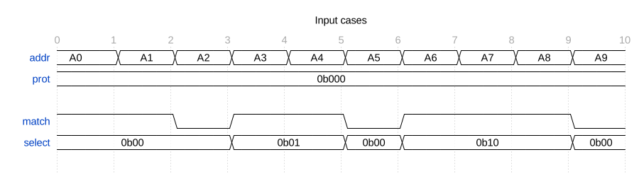
Automatic alignment leaves gaps between enabled address regions
Explicit bases and a disabled slot
Connections and security remain unrestricted. This example sets a nonzero packed base parameter, so all slots use their explicit bases:
.M_BASE_ADDR({16'h7000, 16'h6000, 16'h2000, 16'h4000, 16'h1800, 16'h0000})
Target |
Region |
Width |
Configured base |
Effective address range |
|---|---|---|---|---|
M0 |
0 |
8 |
|
|
M0 |
1 |
0 |
|
Disabled |
M1 |
0 |
10 |
|
|
M1 |
1 |
8 |
|
|
M2 |
0 |
9 |
|
|
M2 |
1 |
8 |
|
|
M0’s zero base is a valid explicit address. Its disabled region remains
absent despite the nonzero 0x1800 base. M1’s region 1 lies below its
region 0 in address order; packed slot order does not constrain explicit
placement. The earlier automatic location 0x0400 no longer selects M1.
Label |
Address |
Meaning |
|---|---|---|
|
|
Explicit M0 region |
|
|
Old automatic M1 location, now unmapped |
|
|
Configured base of the disabled slot |
|
|
M1, region 1 |
|
|
M1, region 0 |
|
|
First byte beyond M1’s region 0 |
|
|
M2, region 0 |
|
|
First byte beyond M2’s region 0 |
|
|
M2, region 1 |
|
|
First byte beyond M2’s region 1 |
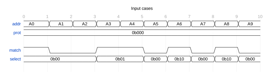
Explicit bases preserve holes while a zero-width slot remains disabled
Source connectivity and security qualification
This example retains the explicit map. Two decoder instances with S = 0
and S = 1 observe the same address and PROT inputs. Both use
M_CONNECT = 6'b011011 and M_SECURE = 3'b100:
Target |
Source S0 |
Source S1 |
Security rule |
|---|---|---|---|
M0 |
Connected |
Connected |
Secure or nonsecure |
M1 |
Disconnected |
Connected |
Secure or nonsecure |
M2 |
Connected |
Disconnected |
Secure only, PROT bit 1 zero |
Label |
Address |
Meaning |
|---|---|---|
|
|
M0 |
|
|
M1, region 1 |
|
|
M2, region 0 |
|
|
M2, region 1 |
|
|
Disabled region |
|
|
Unmapped address |
M0 matches for both sources with PROT 0b000 and 0b111. M1 matches
only for S1, with either secure or nonsecure attributes. M2 matches only
for S0 when PROT bit 1 is zero: 0b000 and 0b101 are permitted,
whereas 0b010 is rejected. The same target rules cover both of M2’s
regions. Neither source matches the disabled slot or the unmapped address.
Changing PROT bits 0 and 2 alone does not change the result.
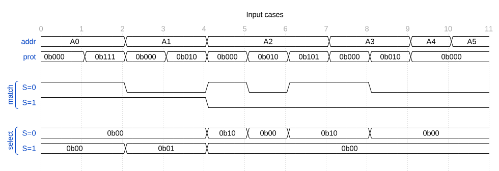
Source connectivity and PROT qualify the same address independently