AXI4-Lite crossbar – openenoc_axil_crossbar
Connects several AXI4-Lite initiators to a shared set of memory and register targets.
Source: openenoc_axil_crossbar.sv.
Parameters
Name |
Default value |
Allowed values |
Description |
|---|---|---|---|
|
|
Integer >= 1 |
Number of upstream initiator interfaces. |
|
|
Integer >= 1 |
Number of downstream target/output interfaces. |
|
|
Integer >= 1 |
Byte-address width in bits; connected interfaces must agree. |
|
|
One positive 32-bit count per source |
Routing-context capacity per source in each read/write path. Source 0 occupies the least-significant slice; buffered responses are additional. |
|
|
Integer >= 1 |
Number of decode regions per target. |
|
|
Packed aligned addresses; zero selects automatic placement |
One ADDR_W-bit base per target region; region index m*M_REGIONS+r starts in the least-significant slice. |
|
|
Zero, or log2(STRB_W)..ADDR_W in crossbar integration |
Region span is 2**width bytes; zero disables the region. Packing follows M_BASE_ADDR. |
|
|
M_COUNT*S_COUNT-bit mask |
Permitted read paths; bit m*S_COUNT+s connects source s to target m. |
|
|
M_COUNT*S_COUNT-bit mask |
Permitted write paths; bit m*S_COUNT+s connects source s to target m. |
|
|
One positive 32-bit count per target |
Routing-context capacity per target in each read/write path, including buffered requests. Target 0 occupies the least-significant slice. |
|
|
M_COUNT-bit mask |
A set bit disallows nonsecure accesses to that target. |
Signals
Interface ports contain channels in both directions. The table identifies the selected modport or stream role; member directions follow that interface.
Name |
Type |
Direction / role |
Description |
|---|---|---|---|
|
|
input |
Common clock for both fabrics and all connected interfaces. |
|
|
input |
Active-high synchronous reset of routing, arbitration, and channel buffers. New source request acceptance is inhibited while reset is asserted. |
|
|
bidirectional (wr_slv) |
Incoming AXI4-Lite write channels. |
|
|
bidirectional (rd_slv) |
Incoming AXI4-Lite read channels. |
|
|
bidirectional (wr_mst) |
Outgoing AXI4-Lite write channels. |
|
|
bidirectional (rd_mst) |
Outgoing AXI4-Lite read channels. |
Architecture and operation
The wrapper combines the independent read and
write fabrics. Source index s identifies the
upstream initiator connected to s_axil_rd[s] and s_axil_wr[s];
target index m identifies the downstream slave on m_axil_rd[m] and
m_axil_wr[m]. Reads and writes have separate arbitration, routing state,
capacity limits, and responses. They can progress concurrently, including
when they address the same target. Different targets arbitrate independently.
Each target has round-robin AR and AW selection among eligible sources. After reset, a tie starts with source 0; accepting an address advances that target’s corresponding priority. Requests admitted to an empty address buffer appear at the downstream interface in the following interval. After the pipeline fills, an unstalled target can receive an address every cycle. The address decoder selects the target from the address and PROT attributes. Addresses are forwarded unchanged.
Each target AW, W, and AR channel, and each source B and R channel, uses a two-entry AXI4-Lite channel register slice (skid buffer). These buffers hold VALID and payload stable during backpressure. AW admission establishes the W route, so source W acceptance starts after its AW has been admitted. W can then progress independently of the downstream AW handshake, while its association with the correct source and target is retained.
Responses retain the request order separately for each source’s read and write streams, even when consecutive requests address different targets. A faster response from a later target waits until the earlier response can enter the source response buffer. Target response order identifies the requesting source without AXI IDs. A response is then registered before being presented upstream. Read and write response order is independent; there is no combined B/R ordering constraint.
S_ACCEPT and M_ISSUE limit routing contexts separately in each
fabric. Admission reserves a source entry and, for a mapped request, a target
entry, including requests still in a downstream channel buffer. The entries
are released when the response enters the source response buffer. A source
may therefore still hold buffered responses after routing capacity becomes
available for new requests. A response transfer can free capacity for a new
address at the same edge. These limits are not end-to-end counts of all
requests awaiting consumption of their upstream B or R response.
Address regions use target-major packing: region m/r occupies slice
m*M_REGIONS+r in M_BASE_ADDR and M_ADDR_W. A width w enables
a 2**w-byte region; width zero disables it. An entirely zero
M_BASE_ADDR selects automatic aligned placement in that packed order.
Use aligned, nonoverlapping regions. M_CONNECT_RD and M_CONNECT_WR
are independent matrices with bit m*S_COUNT+s controlling source s to
target m. M_SECURE[m] rejects that target’s accesses with PROT[1] = 1.
All connected interfaces must use matching address, data, strobe, and
applicable USER widths.
An unmapped address, a disabled connection, or a rejected nonsecure access
produces local DECERR (0b11) without forwarding that request to a target.
An invalid read returns zero data in its proper source order. An invalid
write first accepts AW and consumes its associated W beat, then returns B
with DECERR. Responses from an accessed target retain that target’s response
code. WSTRB is forwarded with write data.
Reset inhibits new source AW, W, and AR acceptance. At a rising edge with RST high, arbitration, routing queues, and channel buffers are cleared. Already buffered downstream VALID or upstream BVALID/RVALID clears at that edge, rather than combinationally when RST rises. Reset must also clear the connected endpoints’ in-flight accesses so no old request or response is reintroduced after the fabric state is discarded.
Functional scenarios
The examples use two sources, two targets, 32-bit addresses/data, and four
write strobes. S0/S1 denote source indices 0/1; M0/M1 denote target indices
0/1. Each uses the correspondingly indexed public read/write interfaces.
All illustrated writes use WSTRB = 0xF. A0, A1, … identify byte
addresses and D0, D1, … identify data words, local to each scenario.
The configuration is the same in all examples:
.S_COUNT(2),
.M_COUNT(2),
.ADDR_W(32),
.S_ACCEPT({32'd2, 32'd2}),
.M_REGIONS(1),
.M_BASE_ADDR('0),
.M_ADDR_W({32'd16, 32'd16}),
.M_CONNECT_RD(4'b1111),
.M_CONNECT_WR(4'b0111),
.M_ISSUE({32'd2, 32'd2}),
.M_SECURE(2'b10)
Target |
Automatically placed region |
Reads |
Writes |
|---|---|---|---|
M0 |
|
S0 and S1 |
S0 and S1 |
M1 |
|
S0 and S1, secure accesses only |
S0 only, secure accesses only |
PROT is zero except for the explicitly nonsecure request below. A numbered
tick denotes a clock interval; transfers occur at its ending rising edge
when VALID and READY are high. x marks payloads or response codes that
are irrelevant while their VALID is low.
Parallel write and read to independent targets
Access |
Upstream request |
Target |
Result |
|---|---|---|---|
S0 write |
AW and W offered from tick 1 |
M0 |
Successful B response |
S1 read |
AR offered in tick 1 |
M1 |
Successful R response with |
S0’s AW and S1’s AR are both accepted in tick 1. The corresponding target addresses appear in tick 2. S0’s W waits for the write route established by AW, is accepted in tick 2, and transfers to M0 in tick 3.
M1 returns D1 in tick 3 and S1 receives it in tick 4. M0’s B response
transfers in tick 4 and reaches S0 in tick 5. Read progress does not wait
for the write data or B response; the two transactions use independent
request and response paths.
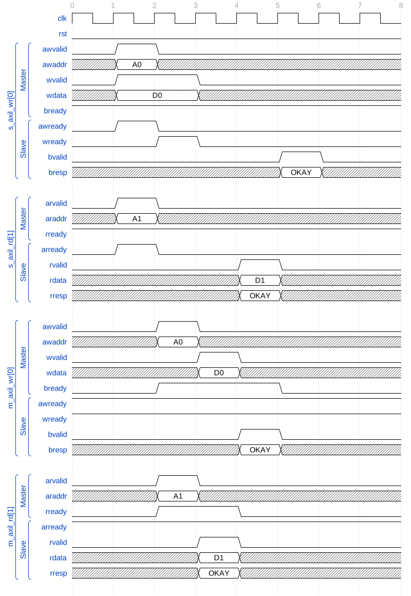
Independent read and write paths advance through their channel buffers
Target contention, capacity limits, and response order
Source |
Address / data |
Target |
Request and response availability |
|---|---|---|---|
S0 |
|
M0 |
Request from tick 1; target response from tick 6 |
S0 |
|
M1 |
Request from tick 2; target response from tick 4 |
S1 |
|
M0 |
Request from tick 1; target response from tick 7 |
S0 |
|
M1 |
Request from tick 3; target response from tick 8 |
S1 |
|
M0 |
Request from tick 3; target response from tick 8 |
Both sources initially request M0. Its reset priority accepts S0’s A0
in tick 1, then S1’s A2 in tick 2. M0 sees those addresses in ticks 2
and 3. S0’s independent request A1 to M1 is admitted in tick 2 and
appears at M1’s target interface in tick 3.
S0 then holds A3 with ARVALID high in ticks 3 through 6. Its two source
routing entries are occupied by A0 and A1. S1 holds A4 over the
same interval because both M0 target entries are occupied by A0 and
A2. Neither request loses its address while waiting.
M1 offers D1 from tick 4, but its RREADY remains low through tick 6:
S0’s earlier A0 response has not yet arrived. M0 returns D0 in
tick 6. Capturing it frees routing capacity and permits both waiting AR
requests to be admitted at that same edge, even though S0 still holds
its upstream RREADY low.
In tick 7, M1’s D1 and M0’s D2 transfer into their respective source
response buffers. S1 receives D2 in tick 8 and D4 in tick 9.
S0’s output holds D0 unchanged in ticks 7 through 10. Its buffer also
retains D1, so M1’s next response D3 waits in ticks 8 through 10.
After S0 resumes, it consumes D0, D1, and D3 in ticks 10, 11,
and 12. The accepted request order survives both differing target latency
and upstream backpressure.
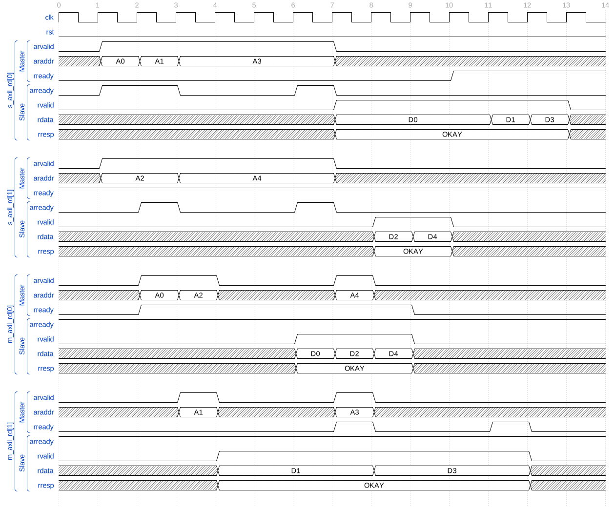
Routing capacity recovers while buffered responses preserve source order
Local errors for address and permission failures
All requests here originate at S1.
Access |
Address / attributes |
Result |
|---|---|---|
Read |
Outside both configured regions |
Local DECERR with zero read data |
Write |
M1, secure |
Local DECERR because the S1-to-M1 write path is disabled |
Read |
M1, |
Local DECERR because M1 requires a secure access |
Read |
Same address, |
Forwarded to M1 and returns |
The unmapped AR is accepted in tick 1 and returns local R/DECERR with zero data in tick 3. The blocked write’s AW is also accepted in tick 1, its W is consumed locally in tick 2, and B/DECERR appears in tick 4. No target AW or W transfer is generated for that write.
The nonsecure read in tick 5 returns local R/DECERR with zero data in tick 7.
Repeating A2 with secure attributes in tick 8 permits routing: M1
accepts AR in tick 9, returns D2 in tick 10, and S1 receives R/OKAY
in tick 11. Only this final read reaches a downstream target.
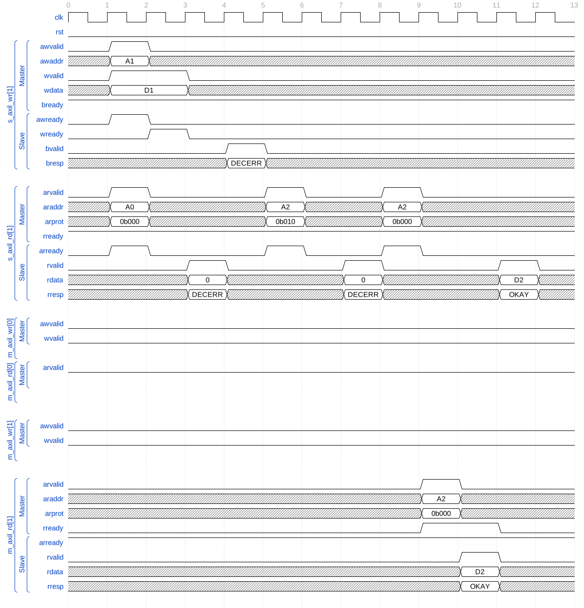
Rejected accesses return local DECERR and only the secure read reaches M1
Reset clears held responses and queued target requests
Both targets reset with the fabric. S0 initially holds RREADY low, and M1 holds ARREADY low until reset is released.
Access |
State before reset |
Result |
|---|---|---|
S0 read |
|
Buffered response discarded |
S1 read |
AR is buffered and waits for target READY |
Queued target request discarded |
S0 read |
Offered after reset |
New request returns |
Both initial AR requests are admitted in tick 1. M0 accepts A0 in
tick 2 and returns D0 in tick 3; S0’s RVALID holds that data from
tick 4. M1’s ARVALID holds A1 from tick 2 because ARREADY remains low.
RST is asserted in ticks 5 and 6. Source ARREADY is already low in tick 5,
but the buffered D0 and pending target ARVALID remain visible until
the reset sampling edge. Both VALID outputs are zero in tick 6. Neither
the held source response nor the unaccepted target request is replayed.
RST is released in tick 7. The registered channel readiness recovers at
that interval’s ending edge, so the new A2 request offered in tick 7
is accepted in tick 8. M1 receives it in tick 9, returns D2 in tick 10,
and S0 consumes the response in tick 11.
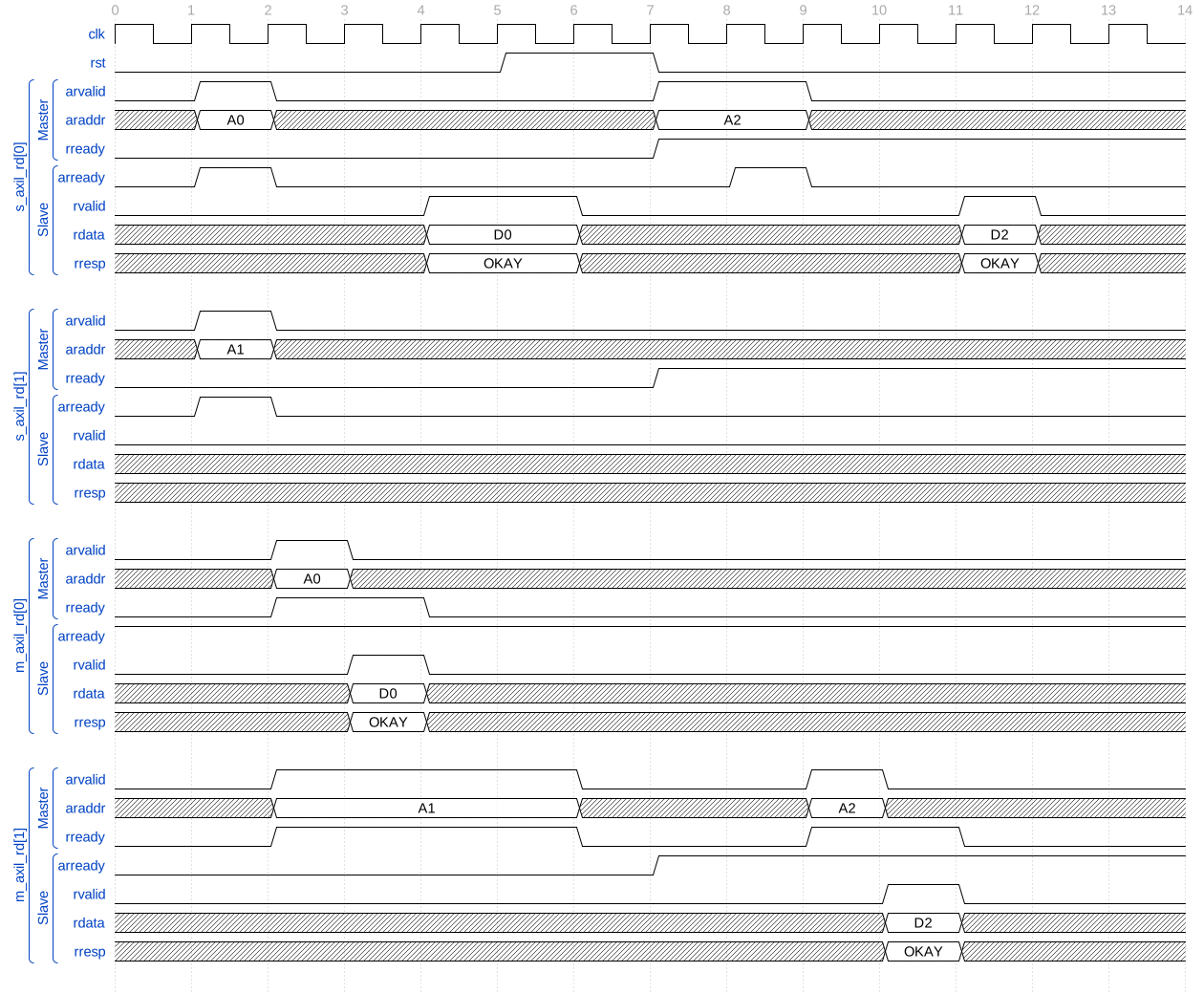
Reset removes a held response and an unaccepted downstream address
Verification
The test suite is in dv/core/openenoc_axil_crossbar/.
Testbench
This cocotb suite verifies the AXI4-Lite crossbar and its address decoder, read/write paths, and channel skid buffers.
Coverage
The suite covers:
address routing, decode errors, and reset;
simultaneous initiators and response ordering across targets;
independent AW/W backpressure and stable stalled payloads;
sustained traffic with consecutive target-side AR, AW, and W handshakes when uncontended.