Bidirectional Ethernet link – openenoc_eth_if
Defines a bidirectional Ethernet-like link using two independent frame streams.
Source: openenoc_eth_if.sv.
Parameters
The tables describe the Ethernet-link profile used by openENOC. Generic TAXI strobe and metadata options remain in the source declaration but are not used on these links.
Name |
Default value |
Allowed values |
Description |
|---|---|---|---|
|
|
Positive multiple of 8 |
Stream data width in bits, shared by both link directions. |
|
|
DATA_W/8 for byte-granular endpoint links |
Number of byte-valid lanes per stream beat. |
|
|
0 or 1 |
Enables byte-valid masks; disabled means every byte lane is valid. |
|
|
1 for Ethernet frame links |
Enables the final-beat marker for Ethernet frames. |
Signals
Directions below are relative to the named link side. Each embedded stream uses the TAXI source/sink roles; READY travels opposite to data.
Name |
Type |
Direction / role |
Description |
|---|---|---|---|
|
|
input |
Clock shared by both directions, supplied by the surrounding integration. |
|
|
input |
Active-high reset for attached logic in the link clock domain. |
|
|
A to B; READY B to A |
Frame stream from side A to side B, with reverse READY. |
|
|
B to A; READY A to B |
Frame stream from side B to side A, with reverse READY. |
Name |
Type |
Direction |
Description |
|---|---|---|---|
|
|
A to B |
Frame data bytes. |
|
|
A to B |
Byte-valid mask when enabled; only the final beat may have a partial mask. |
|
|
A to B |
Final frame beat when LAST_EN is set. |
|
|
A to B |
Current beat is valid. |
|
|
B to A |
Side B can accept a beat; transfer also requires tvalid. |
|
|
B to A |
Frame data bytes. |
|
|
B to A |
Byte-valid mask when enabled; only the final beat may have a partial mask. |
|
|
B to A |
Final frame beat when LAST_EN is set. |
|
|
B to A |
Current beat is valid. |
|
|
A to B |
Side A can accept a beat; transfer also requires tvalid. |
Architecture and operation
The link contains two independent taxi_axis_if instances. Side A drives
a2b_axis_if as a source and receives b2a_axis_if as a sink; side B uses
the opposite roles. Each direction uses ordinary AXIS ready/valid handshakes,
TKEEP for valid bytes, and TLAST for frame boundaries.
DATA_W and KEEP_W set the shared byte-lane geometry. KEEP_EN
selects byte-valid masks, and LAST_EN is required for Ethernet frame
boundaries.
On-chip Ethernet frames exclude preamble, SFD, and FCS. Internal endpoint and switch metadata is used between processing stages, not on the Ethernet links. Stream ID, destination, and user metadata are therefore absent from the Ethernet-link signal tables and timing diagrams.
Functional scenarios
The examples use DATA_W = 32, KEEP_W = 4, KEEP_EN = 1, and
LAST_EN = 1. DA0, DA1, and subsequent labels are
A-to-B data beats; DB0, DB1, and subsequent labels are B-to-A data
beats. Non-final beats have all KEEP bits set; only the final beat may have
a partial byte-valid mask. The full mask is 0xF for the four byte lanes
shown here. A one-byte final beat uses 0x1, enabling only byte lane 0.
Data labels are local to each diagram. Frame lengths of
64 B and 65 B count bytes on this interface, excluding preamble, SFD, and
FCS. The first two diagrams show complete frames; the startup diagram shows
only the beginning of their transfers.
A beat transfers on a rising clk edge when both tvalid and
tready are high. Numbered cycles label intervals between rising edges;
the values in each cycle are sampled at its ending rising edge.
A source holds tvalid, tdata, tkeep,
and tlast stable while a valid beat is stalled. Shaded x regions
mark values that are irrelevant when tvalid = 0; they do not require
drivers to produce unknown values.
Independent traffic in each direction
Side A sends a 64-byte frame on a2b_axis_if as 16 full beats,
DA0 through DA15. Every beat uses tkeep = 0xF, including
the final beat. Side B concurrently sends a 65-byte frame on
b2a_axis_if: 16 full beats, DB0 through DB15, followed by
DB16 with tkeep = 0x1. Only byte lane 0 is valid in that final beat.
Both directions transfer their first beat in cycle 1. In cycles 2 and 3,
side B deasserts a2b_axis_if.tready. Side A holds DA1 and its
qualifiers stable until the transfer in cycle 4, then continues through
final beat DA15 in cycle 18. Meanwhile, side A keeps
b2a_axis_if.tready asserted, so the reverse frame transfers without
a stall in cycles 1 through 17. Its final beat DB16 transfers in
cycle 17. Backpressure in one direction does not prevent a transfer in the
other.
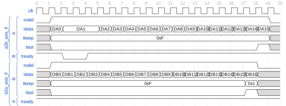
Concurrent 64-byte and 65-byte frames with independent backpressure
Partial final beats
Side A sends a 65-byte frame as 16 full beats, DA0 through DA15,
followed by the one-byte final beat DA16. The full beats use
tkeep = 0xF; the final beat uses tkeep = 0x1, enabling only byte
lane 0. The receiver ignores byte lanes 1 through 3 on that final beat.
tkeep has one bit per byte lane.
The full beats transfer in cycles 1 through 16. Side A presents DA16
with tlast = 1 in cycle 17, but side B keeps tready = 0 in
cycles 17 and 18. The final beat, its byte-valid mask, and tlast
remain stable until acceptance in cycle 19. The frame ends on that
transfer; asserting tlast during a stall does not end it early.
The reverse direction follows the same rules and is omitted here for clarity.
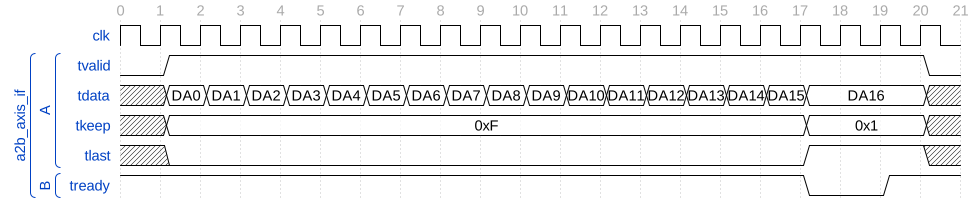
65-byte frame with a stalled one-byte final beat
When KEEP_EN = 0, every byte lane is valid and a partial final beat
cannot be represented. An eight-bit link needs no partial-byte mask because
each beat carries exactly one byte. LAST_EN = 1 still identifies the
final transferred beat.
Endpoint orientation and link clock/reset ownership
The A/B orientation determines ownership of the stream signals:
Embedded stream |
Source: DATA, KEEP, LAST, VALID |
Sink: READY |
|---|---|---|
|
Side A |
Side B |
|
Side B |
Side A |
The Endpoint interface – openenoc_endpoint_interface uses side A: its TX path drives
a2b_axis_if, and its RX path receives b2a_axis_if. A switch port
in its default side-B orientation uses the opposite roles; PORT_SIDE
selects the switch-port orientation.
Both directions of one interface instance share its input clk and
active-high rst. The surrounding integration supplies these signals
and connects the participating logic to the same clock/reset domain.
The interface itself contains no sequential logic, reset gating, or buffering.
In particular, the endpoint module’s separate clk/rst ports must be
connected consistently with the link’s clock/reset inputs.
The diagram shows the start of the same 64-byte A-to-B and 65-byte B-to-A
frames after a shared reset. While rst = 1 in cycles 0 and 1, both
sources keep tvalid = 0. Reset is deasserted in cycle 2. Side A starts
with DA0 in cycle 3, and side B starts with DB0 in cycle 4.
All shown beats have every byte lane valid. Both frames continue beyond
the displayed interval, so neither stream asserts tlast here.
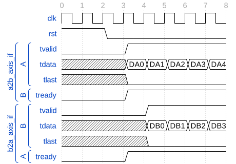
Shared reset followed by the start of 64-byte and 65-byte frames
Reset duration and recovery latency follow the connected modules; the interface does not enforce the illustrated startup delay or READY levels. For connections between different clock domains, use a clock-domain adapter such as Ethernet clock/width adapter – openenoc_eth_adapter between separate local link instances.